
In addition to teardowns, we run 4 electrical tests on our batteries. Each test measures battery characteristics that matter for real-world performance.
The tests:
- Internal Resistance Testing
Measure electrical resistance of entire pack across state-of-charge and report result as an averaged value. - Total Capacity Testing
Discharge a pack from 100% state-of-charge to ~0% at a low rate. Report result in Ah (using 18V as nominal voltage) and Wh. - High-Power Cycling Testing
Discharge batteries, cycling on and off high-power; 800W for 20s on, then 20W for 6s off, until battery depleted, thermal-cutoff achieved, or other failure mode. Report total uninterrupted cycles completed. - Run To Failure Test
Discharge batteries in current-limited steps, at increasingly higher current values, until failure. Test ignores thermal limit cutoffs and smoke and instead runs until mechanical failure (loss of voltage, sustained fire) or electrical failure (V_pack < 2V).
Internal Resistance Test Procedure:
The electrical resistance of a battery is a measurement of its quality. Higher resistance causes more energy to be lost within the pack itself, resulting in lower efficieny and heating within the pack. Low-quality 18650 cells experience overheating at high current, and poor electrical construction results in heating and melting at connections with high resistance.
Pack heating losses scale quadratically with current and overheating quickly becomes a problem for poorly constructed power tool batteries.
Power tool batteries can exceed 100A of current
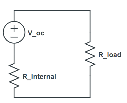
We can measure R_internal by comparing the voltage drop at two different operating currents. We use I_small = 1A, I_big = 15A:
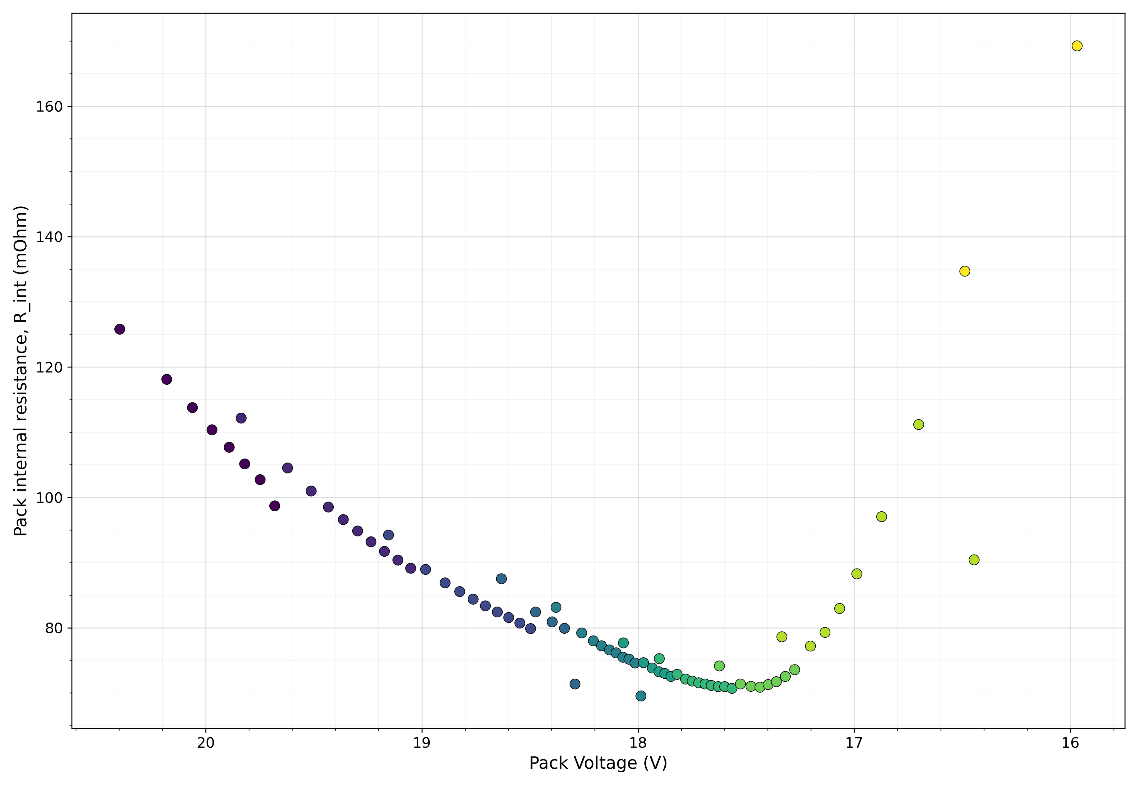
We take measurements at 17.5V < V_pack < 18.5V because it's the most stable regime for internal resistance. We also spend ~30 mins heating up the packs (by running them at 15A) to reach consistent internal temperatures. Internal resistance is a function of pack voltage and temperature
Total Capacity Test Procedure:
High-capacity is often the primary advertising point of power tool batteries. Measured in watt-hours, energy capacity is purely a function of the 18650 cells used. Almost all battery vendors report capacity in Ah, assuming 18V nominal for the pack.
We discharge at low current relative to the battery's Ah capacity, around ~0.2 - 0.5C, to minimize energy lost to heat
The lower the discharge current, the higher the E_delivered; we discharge at 2A.
High Power Cycling Test Procedure:
In actual, intensive use, power tool batteries are typically being cycled on and off, as the user goes about operating their tool. DeWalt tools like circular saws and angle grinders will output ~800W continuous under high loads (as measured by the Torque Test Channel on Youtube), so we cycle batteries repeating 800W for 20s, then 20W (effectively idle) for 6s.
DeWalt batteries and tools use a thermistor reading to determine if a pack is overheating: the tool will automatically cutoff if it's connected to a pack that's too hot. So we monitor for thermistor values and conclude the test when the pack reaches R_NTC > tool-cutoff. Other conditions can stop the test, too. The cutoff criteria for the cycling test are:
- Pack thermistor reports overheating to tool (R_NTC > tool-cutoff)
- Pack starts smoking or smells horrible (since a user would stop at this point)
- Pack otherwise fails electrically (voltage collapses, battery is completely discharged)
Failure Test Procedure:
To better characterize the construction quality and safety of packs, we perform a failure test, where we ignore any thermal or voltage limits and discharge the pack aggressively until it fails. Typical failure modes are cells venting, electrical connections melting, packs catching on fire, or cells failing through reverse-polarization effects.
The test is an increasing ramp of constant-current discharge, typically approaching failure-regime around 60-100A (on the order of ~1000W continuous discharge). Results are reported as the failure mode, as well as the total Wh discharged and the peak-power before failure (W).
Battery performance on the failure test is entered into our Hall of Fame scatterplot.